
ModelVision software, Research and Services
Tensor Research Newsletter
December 2025
Create a full Magnetic Gradient Tensor dataset from your next survey
Our team has been working on the magnetic gradient tensor since the turn of the century because we recognised its potential to extract more useful geological information from the magnetic tensor. We also recognised that it was possible to convert a conventional magnetic survey to the full magnetic gradient tensor. Ever since, we have been developing tools needed to interpret the tensor data and extract the detailed geological information that becomes visible.
Dave Pratt presented a paper on the TMI to magnetic gradient tensor transformation entitled “Large scale magnetic gradient tensor surveys from TMI data” with Jared Townsend from BHP’s Invent division at AEGC 2025.
The characteristics of the magnetic potential field makes it possible to transform the total magnetic intensity survey into a magnetic gradient tensor survey. Figure 1 from the conference presentation captured the important concepts behind the transformation using a realistic model survey to demonstrate the model and transformed comparison.

Figure 1. The computed TMI (Bm) grid image is shown on the left with a white model outline of the vertical polygonal-shaped formations with variable magnetic susceptibilities. Next is the computed Bzz model grid image with a rectangle defining an area for detailed comparison with the transformed Bzz tensor component. Contours of the model Bzz for the rectangular sub-area are shown in red, and the black contours show the equivalent FFT transformed contours.
You can use ModelVision to create the full tensor survey. All you need is the original flight lines and the TMI grid. If you have the Depth Module, then the whole process is automated in the QuickDepth application which uses the magnetic tensor to assist in the anomaly classification, azimuth and depth estimation.
The best question from the conference presentation was on magnetic remanence and the TMI to tensor transformation.
Does it work correctly in the presence of remanence?
The answer to this question is yes, because the measured field is a potential field. The TMI field is only dependent on the resultant magnetisation vector which produces the potential field surface. The transformation will also work in the presence of susceptibility anisotropy and demagnetisation, both of which rotate the resultant magnetic vector away from the IGRF direction. The presentation did not include a test with remanence, so remanence was added to three of the original bodies and Figure 2 illustrates the ModelVision results with extremely small difference between the contour sets from the model and transformed grids.

Figure 2. shows screen captures from ModelVision enlargement of two sub-areas where bodies 1, 2 and 3 are remanently magnetised. The contours in the two Bzz maps show both the theoretical model Bzz in red and the transformed Bzz in black. The difference is barely perceptible.
The tensor transformation was applied to a high resolution tensor-ready survey along the length of the Agnew-Wiluna nickel belt in Western Australia. The term tensor-ready was coined to recognise the advantages of flying a survey to optimise the gradient field as opposed to the total magnetic field. Dave also presented another paper on aliasing where he showed a new method for estimating aliasing and charts developed by David Clark for direct estimation of gross aliasing for different target shapes. These methods help to optimise survey specification for geological mapping and direct targeting where applicable.
The tensor transformation method was applied to the region surrounding the Olympic Dam, Carrapateena and Prominent Hill domains. We chose Prominent Hill to illustrate some of the outputs available from the rock property and depth mapping (RPDM) process. Figure 3 shows an image of the TMI and the upper diagonal matrix of the magnetic gradient tensor.
We invert the third column to convey a normal presentation for normally magnetised geology where the z components are negative in the southern magnetic hemisphere. The line spacing for this survey was 200 metres and the flying height was just 65 metres, which is sub-optimal from an aliasing perspective if there are laterites on the ground surface. For our processing we upward continued the data by 100 metres to optimise the gradient tensor results with no loss of resolution with respect to target depths ranging from 100 to 500 metres.
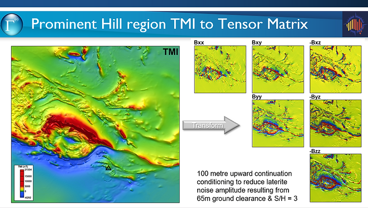
Figure 3. A TMI image and its magnetic gradient tensor upper diagonal matrix representation. The data was upward continued by 100 metres to make it tensor-ready prior to transformation.
Figure 4 illustrates an example of two different presentations of the final depth results from RPDM processing. On the left are the full set of results without any filtering. On the right the results have been filtered for quality which factors in interference, anomaly amplitude, azimuth and nearby results. The quality parameter is used to modulate the size of the symbol which makes it very easy to pick just the highest quality results.

Figure 4. RPDM depth results for all solutions and an AI subset that accounts for noise, interference, amplitude and several other factors collected during the muti-stage process and inversion.
As part of the RPDM process, we collect two parameters called dimensionality (DI) and structural index (SI). DI has a range from 0 to 1 where 0 corresponds to a geological edge or linear magnetic anomaly and 1 corresponds to pipe of ellipsoid. By comparison, SI has a range from ~0.5 to 4 and the extra range means that it can differentiate between ellipsoids and pipes as well as linear formations and straight geological boundaries. Unfortunately, SI is more sensitive to noise and interference from adjacent anomalies. By using the two factors together and anomaly quality information we can isolate the highest quality solutions (Fig. 5) to try and pick out magnetic targets with limited depth extent. Both DI and SI are high in this case. While this is useful for targeting IOCG style deposits, in a mature area like the Olympic Dam province, most have been tested. Limited depth extent targets are also important for identifying possible dilation zones where magnetite may represent one phase of alteration, but it is possible that subsequent dilations were responsible for mineralisation deposition. This implies structural intersections that may not be obvious in the neighbouring magnetic expression.
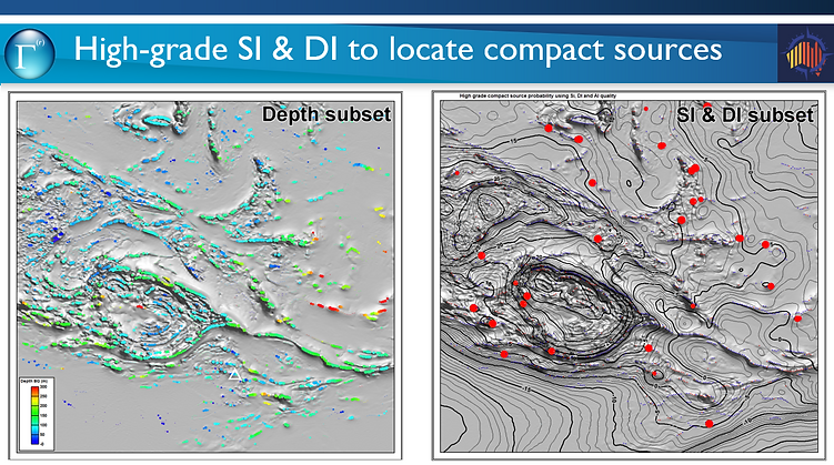
Figure 5. Colour-coded depth symbols (left) and compact source symbols (right) displayed over images of the normalised source strength (NSS). The SI and DI parameters are combined into a compact source parameter that is qualified by their amplitudes and solution quality.
For anyone interested in a full copy of the presentation, please contact us at support@tensor-research.com.au.
ModelVision AI Assistant
The AI assistant has been renamed ModelVision Assistant and is accessed when you press the F1 help key or a help button inside ModelVision.
You can also access the interactive User Guide on the ModelVision documentation portal with this link –
https://documents.tensor-research.com.au/articles/#!modelvision-18-0-help/mv-18-0-help-title-page
or go to the Tensor Research ModelVision Support page as shown in Figure 6.


Figure 6. Image of the new Support page links.
Magnetic Mentor - depth of penetration
Dave has published two more articles in the Magnetic mentor series with both focused on depth of penetration beneath the magnetic unconformity surface. The October issue looked at penetration depth for total magnetic intensity and the first vertical derivative illustrated by a quantitative analysis that demonstrates that it is smaller than you intuitively expect (Fig. 7). For example, approximately 90% of the magnetic contribution comes from a basement slice immediately beneath the unconformity with a thickness equal to the unconformity depth beneath the magnetic sensor. The thickness halves for the first vertical derivative.
The December issue shows how you can use the pseudo-gravity transformation to increase the effective depth of penetration. The depth of penetration effectively doubles compared with TMI when using the pseudo-gravity transformation. You will find supporting data and reference material online by following the links.
Datasets and reference material for the magnetic mentor series are available with the link to each article.

Figure 7. 1VD (a) and TMI (b) inversion curves for the green, orange and red formations after susceptibility inversion of the 10 000 m deep formation model (blue) data. The percentage contribution to the field response is shown beside each formation segment.
Licence transfer/return via email – potential problems
The process to transfer a ModelVision licence to a new computer or back to Tensor Research (return or park) is described in the Licence Manager User Guide. This process requires an email to be sent directly from the Licence Manager and users sometimes have issues with their email security that prevents the email being sent. It is also possible that the series of dialogs about this email may be hidden behind other dialogs/windows and not actioned (i.e. clicking the Allow button). This situation can also apply to activation requests.
You should see the following sequence of dialogs after clicking Create Transfer Activation Code or Automatically Activate (to submit an activation request).

If you suspect that a licence return was not successfully sent, email a copy of the Transfer_Log.txt file, which located in C:\ProgramData\Encom, to support@tensor-research.com.au as confirmation of the licence return. This folder may be hidden, if so, you will need to change your folder settings to show all hidden folders and files.
When transferring a licence to another computer, if the transfer code is lost, it can be retrieved from the Transfer_Log.txt file on the originating (source) computer.
If you suspect an activation request email was not sent, send a screen capture of the Activate Licence tab to support@tensor-research.com.au and we will send an activation code.
We wish you an enjoyable festive season and some down time with family and friends.
Dave, Kerri, Blair & Tony
David.Pratt@tensor-research.com.au
PO Box 5189, Greenwich NSW 2065 Australia
